Non-Electric Condensate Pumps (CCP)

CEMLINE® non-electric condensate pumps have many advantages. There are no impellers or seals, or cavitation problems and no electricity is required. Condensate is efficiently moved at reduced operating cost.

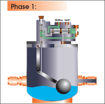
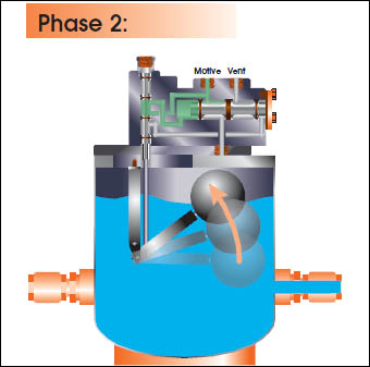
CEMLINE Condensate Pumps (CCP Series) use compressed air or steam as a motive force to move condensate. Condensate from steam systems needs to move from points of lower elevation to points of higher elevation, from points of lower to higher pressure, or from a vacuum to a point of higher pressure or elevation.

Traditionally, condensate is transferred with the use of electrically operated condensate pumps. When moving condensate with electric pumps, the electric pumps tend to wear out quickly. Electric condensate pumps have impellers and seals which can wear, leak, or break down due to harsh condensate environments. The benefit of using non-electric condensate pumps instead of electric condensate pumps is the non-electric condensate pumps have no impellers or seals to wear, requiring less downtime and maintenance. In addition, some remote locations exist where electrical service is not readily available or it is hazardous to use electricity.

Additional benefits from the use of non-electric condensate pumps is the reduction of operating costs associated with returning hot condensate to the boiler. Typically, electric condensate pumps require the condensate flash to atmospheric pressure and decrease in temperature before being pumped to the boiler. The non-electric condensate pumps reduce costs compared to electric condensate pumps because the non-electric condensate pumps can return condensate to the boiler at a higher temperature, which reduces the heating costs required to re-heat the condensate. Along with the reduced expense of re-heating of condensate, less water treatment chemicals are required and less make up water is required to be added to the system.

  • STANDARD EQUIPMENT

    Vessel

    The pump body can be manufactured out of carbon steel or cast ductile iron.

    Mechanism

    The stainless steel mechanism is made from 316 stainless steel. Either a piston powered mechanism or a single spring reducing wear on the snap action mechanism are available.

    316 stainless steel check valves

    The 316 stainless steel check valves are corrosive resistant and have low cracking pressures for easy opening during the pumping cycle.

    Sight Glass

    The brass sight glass allows for easy viewing of the water level in the condensate pump and easy trouble shooting of the condensate pump when required.

  • OPTIONAL EQUIPMENT

    Skid Mounted with Receiver Tank

    CEMLINE can supply a skid mounted prepackaged unit with an A.S.M.E. rated receiver tank. Packages available are either simplex or duplex condensate pumps. The packaged systems include receiver tank gauge glass, shut off valves, and a skid.

    Cycle Counter

    The cycle counter is available in either electric or mechanical. It counts the number of cycles the mechanism has made.

    Insulating Jacket

    Insulating jacket – The insulating jacket reduces heat loss of the condensate in the tank.

  • PUMP MECHANISM

    The Cemline Piston Powered Condensate Pump is uniquefrom the other non-electric condensate pumps in that it is springless. Thisupdated reliable springless design uses a dual piston type configuration thatacts as a spool selector to shift the valve positions. The pump is able to workwith up to 250 PSI motive steam pressure. It can operate from almost no loadto it’s rated maximum capacity. The piston powered condensate pump haseasy maintenance, is interchangeable with most current spring pumps out onthe market today and is made of all stainless steel components. This designsolves the poor reliability issue of the spring snap mechanism of the past. In addition, the piston powered condensate pump due to a larger orifice,less friction and longer travel, has an increased capacity over the springmechanism pumps. This may allow for a smaller pump than before thereforesaving you valuable space and money.
    The below illustrations demonstrate how non-electrical condensate pumps work during the three step process of moving condensate.

    Step 1. Fill Stage

    Gravity causes condensate flow from the receiver tank through the inlet check valve into the pump tank. At this point the outlet check valve and the motive force valve are closed. The vent valve is open allowing for equalization of pressure between the receiver and the pump tank
    Step 2. Dishcarge Stage

    The condensate fills the pump tank until the pump mechanism opens the motive force valve and simultaneously closes the vent valve.With the motive force valve open, the pump tank begins to pressurize as the motive force pressure becomes great enough to close the inlet check valve. When the pressure in the pump tank becomes greater than the pressure at the outlet check valve, the outlet check valve opens and condensate is discharged from the pump tank into the condensate return piping. Because the inlet check valve is closed condensate is stored in the receiver tank.
    Step 3. Equalization Stage

    The condensate is pumped out and reaches a low level causing pump mechanism to close the motive force valve and open the vent valve. The outlet check valve closes when the pressure in the pump tank is less than that of the outlet line. At this time the inlet check valve is also closed. Then the pressure in the pump and the receiver equalize so that the inlet check valve will open and the fill cycle will begin again.


    The illustrations below demonstrate how the springless piston powered non-electrical condensate pumps work during the four step process of moving condensate.


    At the beginning of the cycle, the pump is empty, the float and the connected primary piston are in the down position and the secondary piston is to the left. Filling the pump with liquid gradually raises the float and the primary piston simultaneously.

    When the tank is filled the float rises until it reaches to the top of its travel causing the connected primary piston to open the port, which directs the motive pressure to the left side of the secondary piston pushing the secondary piston to the right.

    With the secondary piston pushed all the way to the right, the motive pressure pathway to the vessel is open allowing motive pressure to pressurize the tank. Pressurizing the tank forces the liquid to flow from the vessel through the outlet check valve into the condensate return piping.

    In the final phase, the float and primary piston fall as the motive pressure has forced the liquid out of the vessel. When the float and connected primary piston reach the bottom of their travel, the primary piston opens the port that directs the motive pressure to the right side of the secondary piston. The motive pressure pushes the secondary pressure to the left preventing motive pressure from entering the tank and opening a pathway between the tank and the vent. Finally, the vessel’s pressure is vented and the unit is ready to fill and repeat the cycle.

  • APPLICATIONS

    Typical installations would be remote locations, hazardous environments or any application where electrical pumps fail rapidly.